A brief miniHIL overview
Hardware Overview
The default hardware package for the miniHIL consists of the following parts:
-
The miniHIL board itself
-
24V power supply
-
ST-Link/v3 debugger with USB cable
-
STM32 Nucleo board (optional)
-
Some jumper wires
-
One mini USB cable
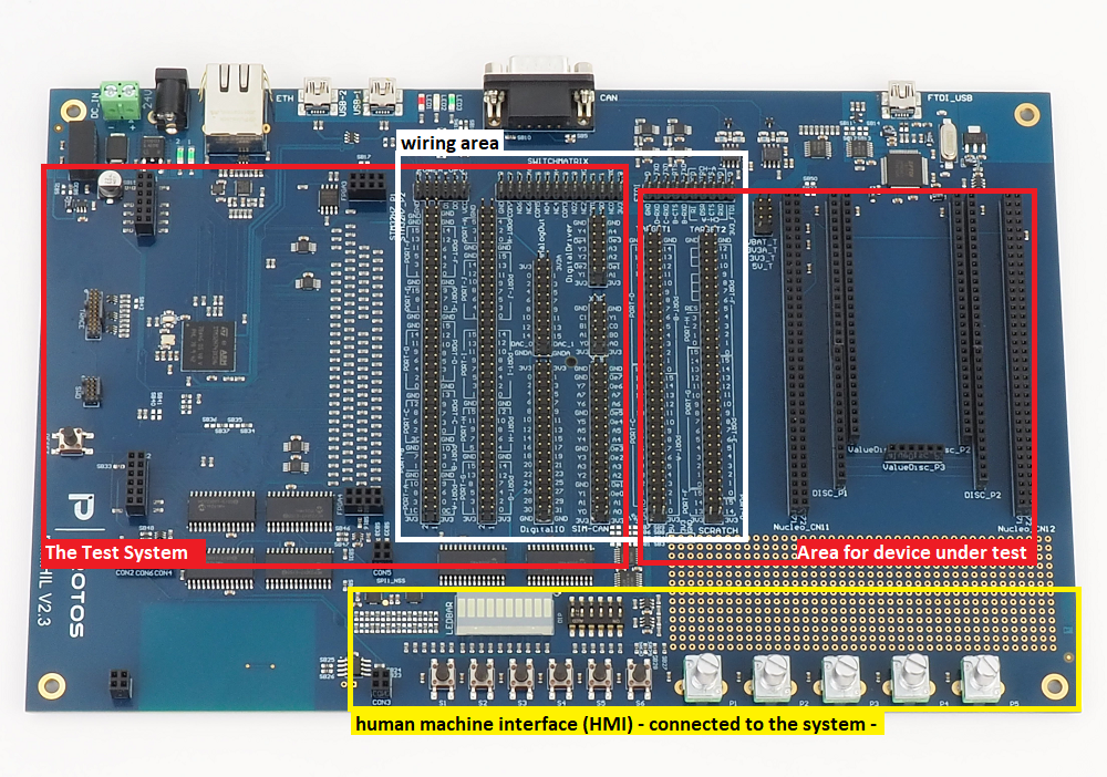
The miniHIL board is split into two parts. On the left side it contains an STM32H743 microcontroller and some additional periphery which is used to handle test case execution, generate the desired stimuli and validate the reactions of the device under test. On the right side the miniHIL board is dedicated to the device under test. It provides connectors and infrastructure for the provided STM32 Nucleo board and some other evaluation kits. The multi-pin connectors in the center of the miniHIL board should be used to connect the pins of the device under test to the test system using jumper wires.
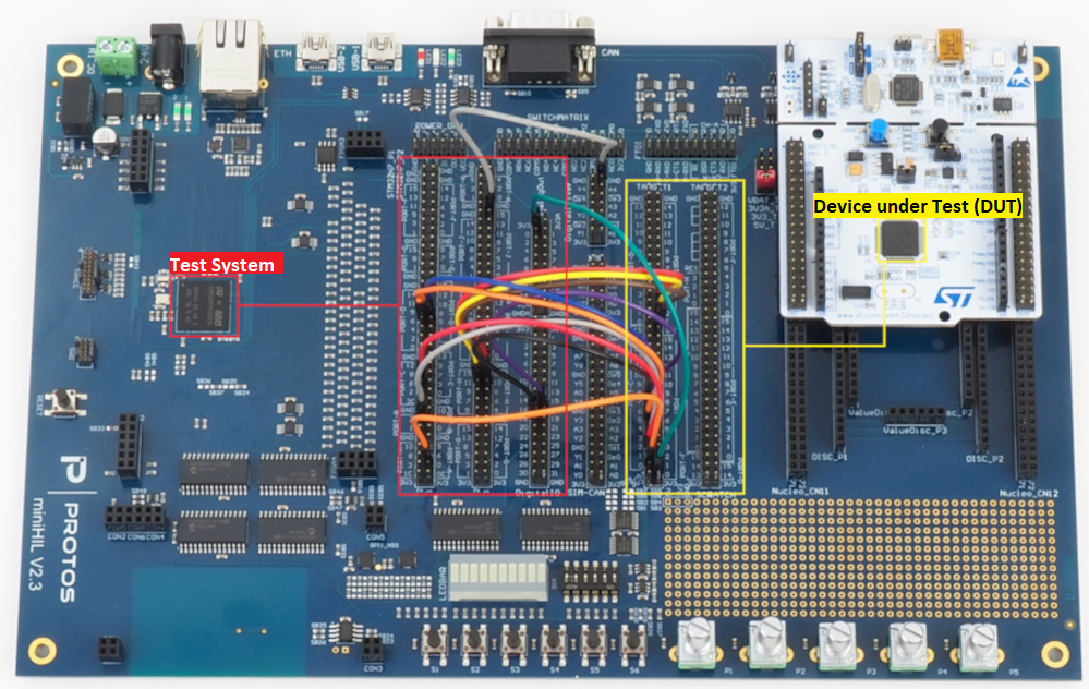
Follow the getting started tutorial to learn how the parts of the default hardware package should be connected to run your first test case.
For a more detailed description of the miniHIL hardware take a look at the Hardware reference documentation.
Software Overview
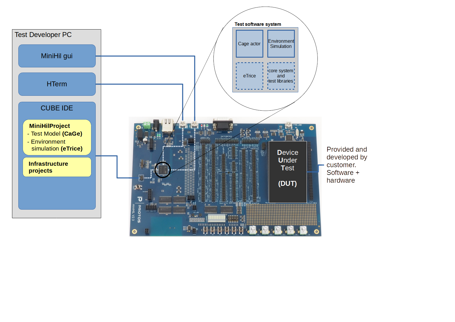
The software used on and with the miniHIL board can be split in three groups:
-
Software run on a test developers computer
-
CUBE IDE: Coding and Modeling for Tests (CaGe) and Environment Simulation (eTrice)
-
miniHIL GUI: Graphical User Interface for Stimulation, Monitoring and Test Execution
-
Commandline API for Test Automation
-
Code Generators
-
Gradle build system to generate, compile and run test system
-
-
Software run on the test system (left side of miniHIL board)
-
Environment Simulation (generated from eTrice Models)
-
Testcases (generated from CaGe Models)
-
System and Test libraries
-
-
Software run on the device under test (right side of miniHIL board)
-
Is provided and developed by customer
-
Test System Software
The test system software which is run on the STM32H743 microcontroller on the left side of the miniHIL board is a combination of different software parts.
-
Framework provided by PROTOS
-
SimModelLib
-
Test und platform libraries and abstractions on model level
-
-
SimRuntime
-
CaGe and eTrice runtime implementation for the test system
-
-
CubeProject
-
Handles basic hardware configuration and low level hardware abstraction
-
-
HILSimGUI
-
The HILSimGUI provides a simple user interface to the test system. It can be used to run tests or to view and change some in-/outputs
-
-
-
Area which should be edited by the user
-
MiniHILProjekt: This project is used by the test developers and the developers of the environment simulations. It contains the eTrice models of the test system including libraries and actors needed for user specific environment simulations. Additionally, this project contains CaGe models which specify the test suites and test cases.
-
The reference documentation on the miniHIL hardware, software and development can be found at Reference.