"Quick" Start 
Prerequisites
Included in the PROTOS miniHIL package you should find:
-
the PROTOS miniHIL board
-
a 24V power supply
-
Wire jumpers
-
USB cable
You should also have received login details for the PROTOS download site where you can download the latest version of the miniHIL software packages (https://dl.protossoftware.de).
Overview over the hardware
The picture below gives an overview over the PROTOS miniHIL hardware.
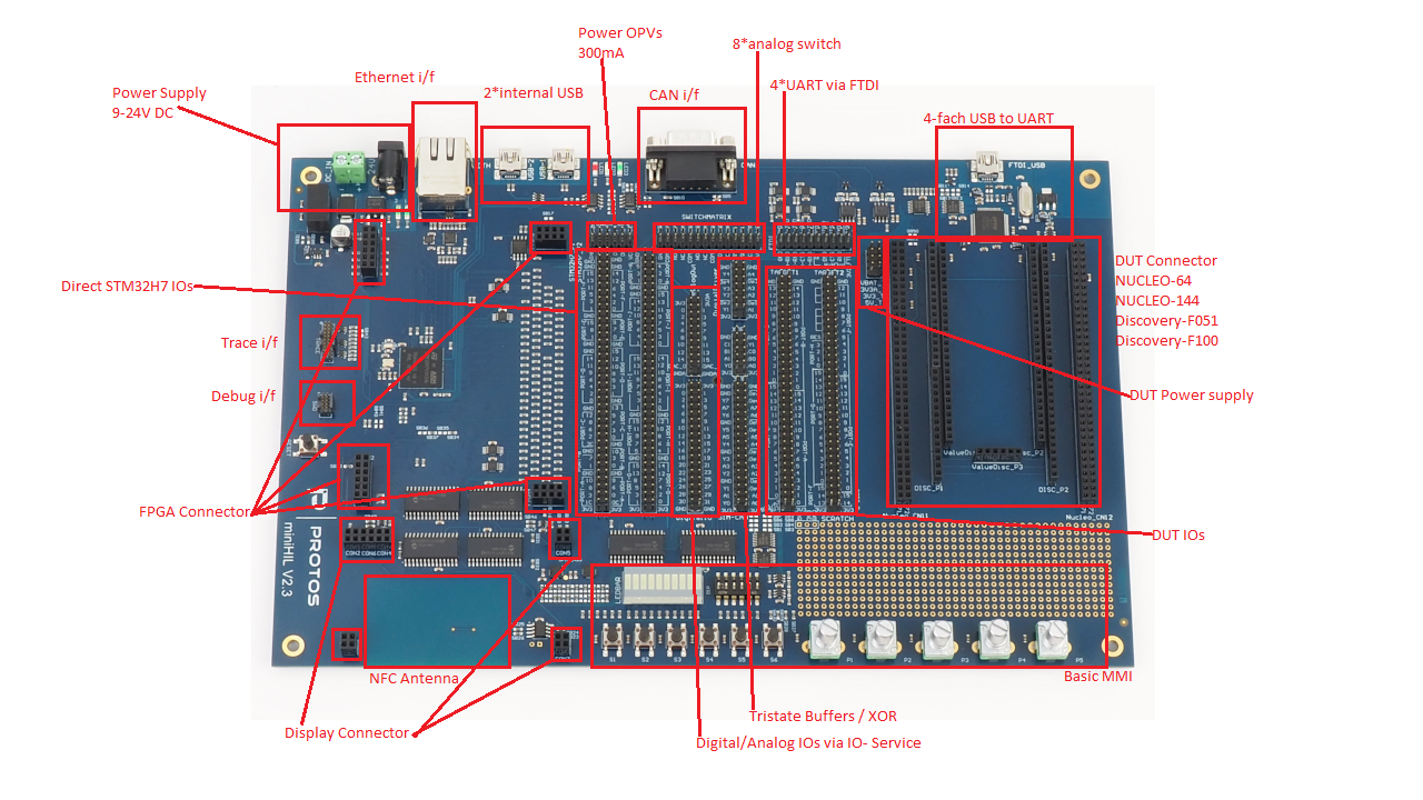
In the Hardware section you can find the detailed definitions and functionalities of PROTOS miniHIL hardware.
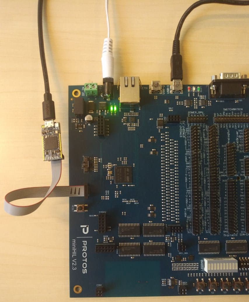
Setting up the hardware
-
Connect the ST-Link debugger to the SWD port on the miniHIL board and the PC
-
Connect the USB-1 port on the miniHIL board to the PC
-
Connect the power supply to the miniHIL board and plug it in to a power socket.
The correct hardware configuration is shown in the image below. Notice the two green LED’s on the top left of the board, which will turn on when the miniHIL board is powered correctly.
Installing the software
Firstly navigate to the PROTOS miniHIL download page (https://dl.protossoftware.de/minihil) and download the following zip files:
-
Example Project
-
MiniHil IDE
-
External Tools
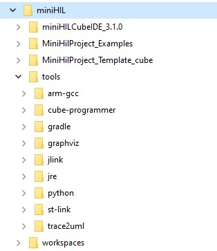
Now create a folder called "miniHIL" in your computer’s root directory. The path of this folder should be C:\miniHIL. Then extract the contents of each .zip file into the newly created miniHIL directory and copy the .zip files of the Example Project, the WorkingLight Project and the Template Project into this folder as well. Ensure, that you haven’t created subfolders inside tools and miniHILCubeIDE after extracting the zip files.
Create a new empty folder named workspaces, which is where the workspace data from your projects will be stored.
Inside the C:\miniHIL directory you should now see this:
 |
While following this user Guide you will apply changes to the Example Project, WorkingLight Project and the Template Project, but also might want to access an unchanged Project later. You can then simply extract the project from the .zip file again. |
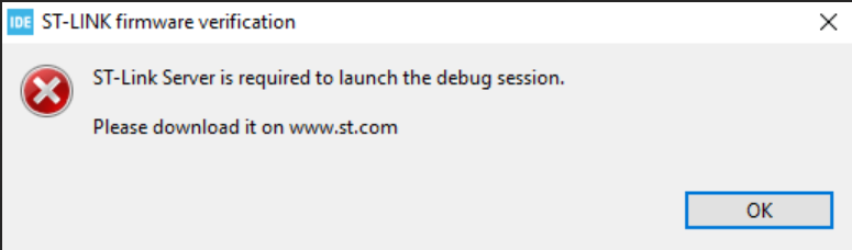
Installing the STLinkServer
To be able to use the run configurations from within the cubeIDE it is necessary to install the STLinkServer Component. You can find the installer in the IDE directory (e.g. C:\miniHIL\miniHILCubeIDE_X.X.X\STLinkServer). Run the installer once. Note that the installer window will only popup briefly and will close itself quite quickly. This is normal. You can find more information about the STLinkServer on the official ST website: https://www.st.com/en/development-tools/st-link-server.html.
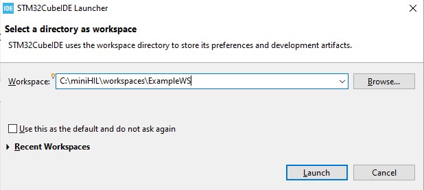
Verifying the miniHIL installation
Launch the IDE (located at C:\miniHIL\miniHILCubeIDE_X.X.X\stm32cubeide.exe) and when prompted, create a new workspace folder inside the C:\miniHIL\workspaces folder (i.e. select C:\miniHIL\workspaces\ExampleWS as our workspace directory)
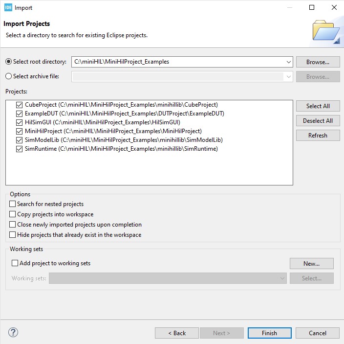
When the CUBE IDE is launched for the first time close the Information Center tab. Then go to File → Import → General → Existing Projects into Workspace and select C:\miniHIL\MiniHilProject_Examples as the root directory. You should see the following projects appear in the main window. Click Finish and allow the import process to finish.
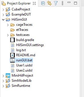
Your Project Explorer should look something like this:
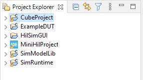
Now your example project is ready to be used.
First build and flash
-
Connect up the ST-Link debugger and the USB-1 port on the miniHIL to your PC.
-
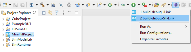
In the IDE, select
build-debug-STLinkin the run configuration dropdown menu. Then click the button to launch the debug mode.
| |
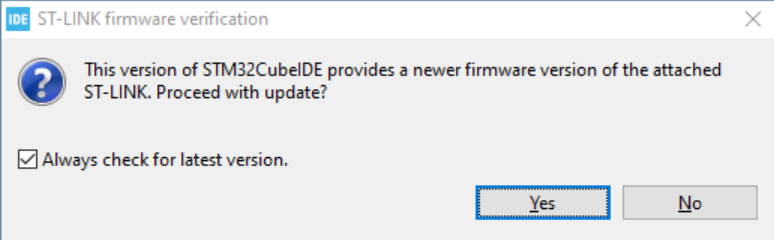
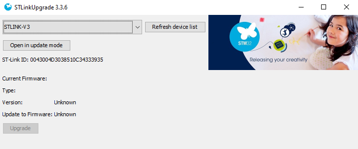
During the first build a popup dialog might prompt you to upgrade the debugger firmware. After you hit OK the update tool will be launched. Just follow the instructions given. (Click on 'Open in update mode', then on upgrade; don’t select the checkbox to change the debugger mode). After you have closed the upgrade tool you have to restart the run configuration. |
-
If building and flashing succeeded, the CUBE IDE switches to the
Debugperspective and stops execution at the breakpoint in themainfunction. Press F8 or hitresumein the toolbar to let the program execute (otherwise there will be no COM port available). -
Go to the HilSimGUI folder in the Project Explorer and double click on runGUI.bat to start up the GUI. A command line window should open up followed by the GUI.
-
At the top left corner of the newly opened window, ensure that the "USB" connection is selected and that the Port selection dropdown window next to it has "Automatic" selected.
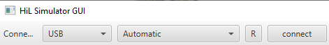
-
Click connect and you should see the elements on the GUI changing to reflect what’s happening on the miniHIL board. For instance, you should notice that the LedBlue element is switching between on and off, to reflect the blinky heartbeat selftest.
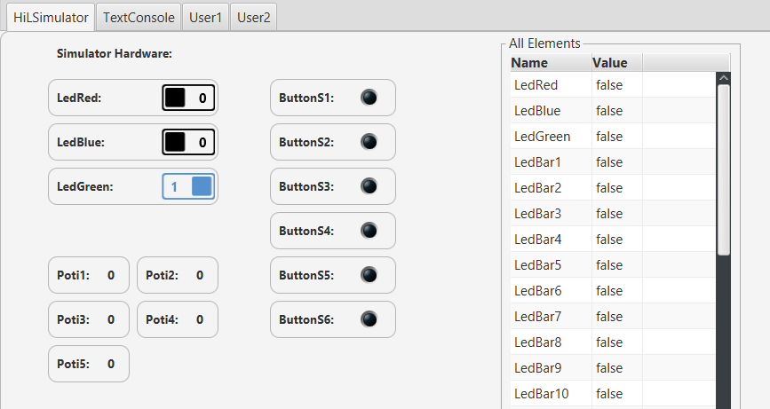
-
We can verify this formally by running its test suite. To run the test suite, navigate to the CaGe menu on the left, select Heartbeat_TestSuite and click on Run Tests.
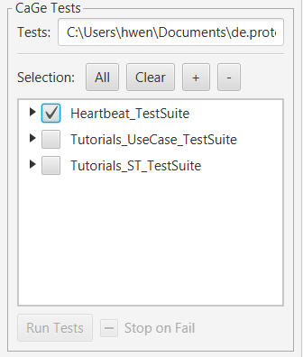
-
If the tests ran successfully, you will see
passedafter each of the tests executed. You have now verified that your miniHIL installation is setup correctly.
Connecting a Device Under Test (DUT)
Included in your miniHIL package, you should find an STM32F303 Nucleo-64 board. We will use this board to demonstrate the Target Device functionality of the miniHIL board.
Connect up the Nucleo board to the miniHIL as per the picture below.
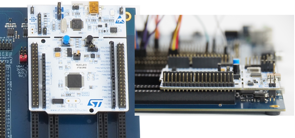
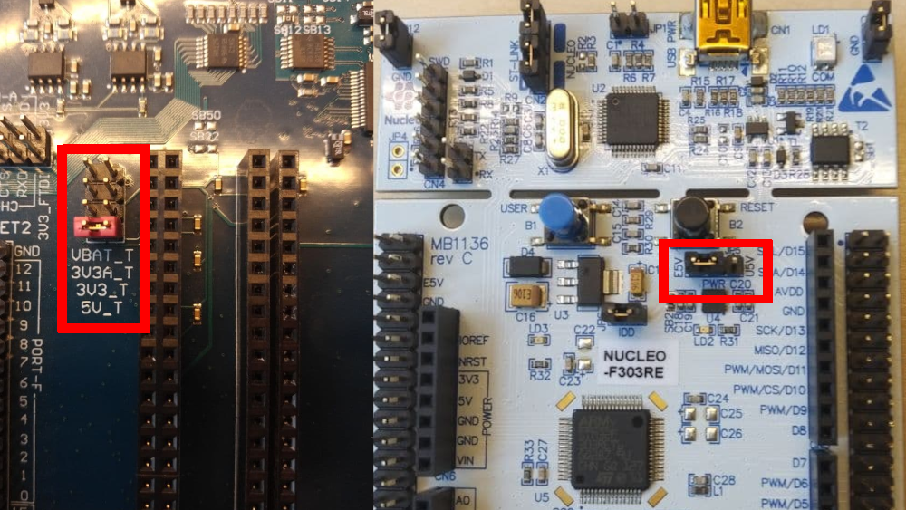
When connecting a Nucleo board to the miniHIL, you should change the power mode of the Nucleo board, so that it gets its 5V via the miniHIL and not via the USB connector.
The STM32F303 also uses an ST-Link debugger. If you have the miniHil-ST-Link and the DUT-ST-Link connected to your PC at the same time, the IDE won’t know which debugger to choose if you want to flash your Project.
You can either disconnect the device you don’t want to flash right now, or you can edit specific Serial Numbers for flashing under Run → Run Configurations
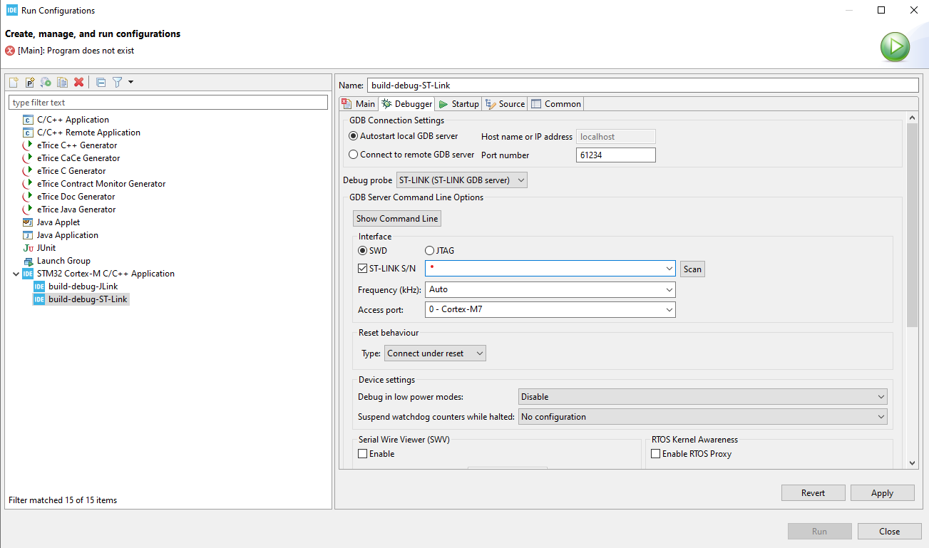
How to find out the SN of your ST-Links:
open C:\miniHIL\tools\st-link in your console, then enter ST-LINK_CLI -List
The cmd-tool will then List all the connected ST-Links with their respective SN.