Interactive Hardware Documentation
Installation
The miniHIL hardware documentation is provided in an HTML file format. Download it from https://dl.protossoftware.de/.
Software Adapter Configuration
-
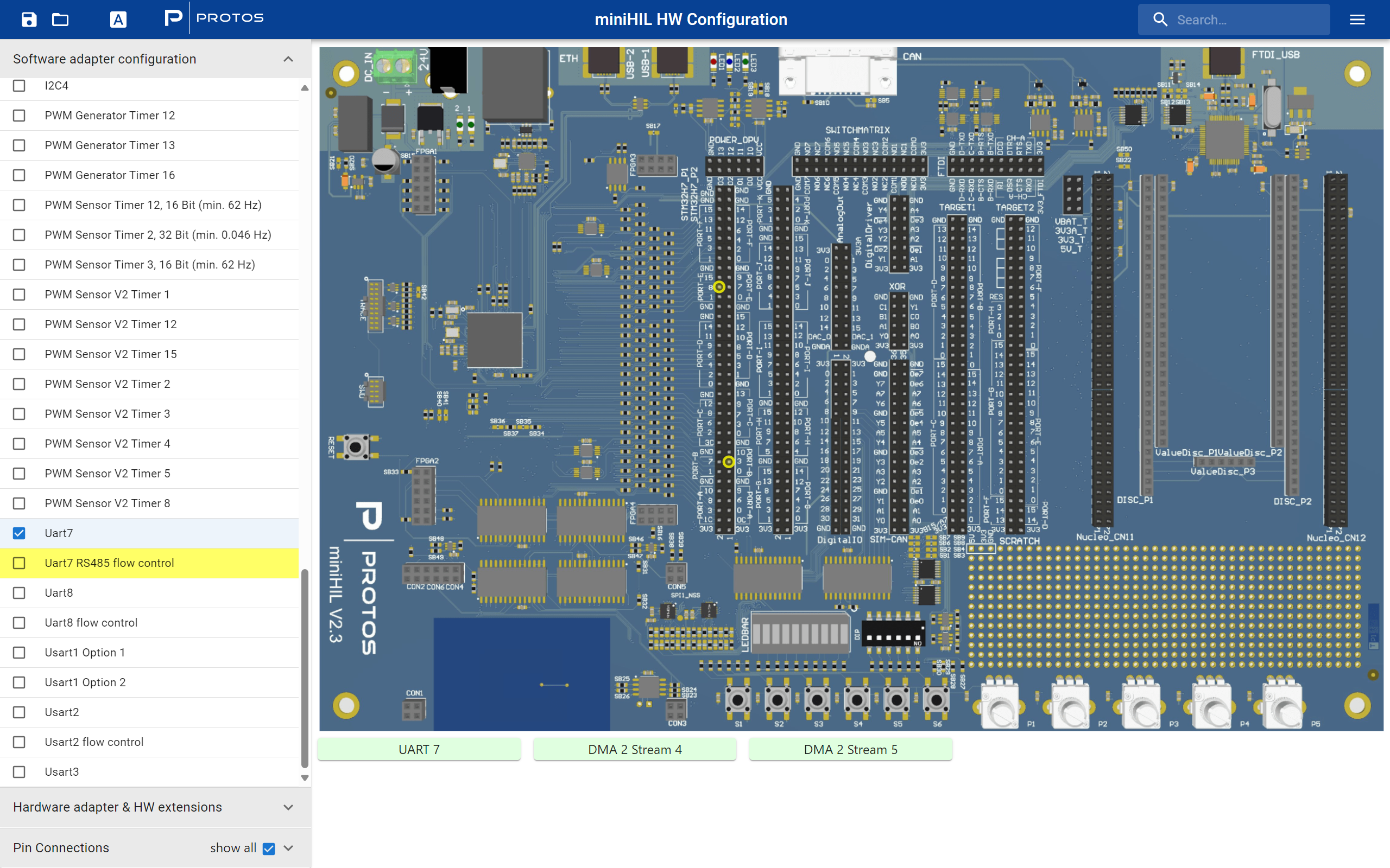
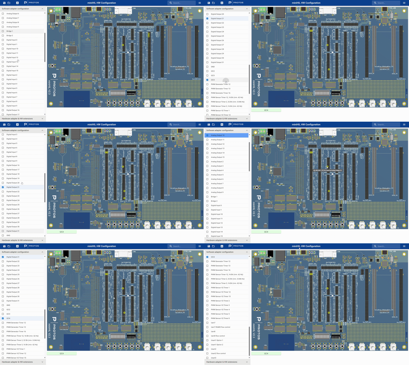
Selecting a Pin: When you select a pin in this section, it will be highlighted with a yellow circle on the interface.
-
Pin Conflict Warning: If there is a conflict with the selected pin (e.g., if another pin uses the same configuration), the conflicting pin names in the list will turn yellow.
-
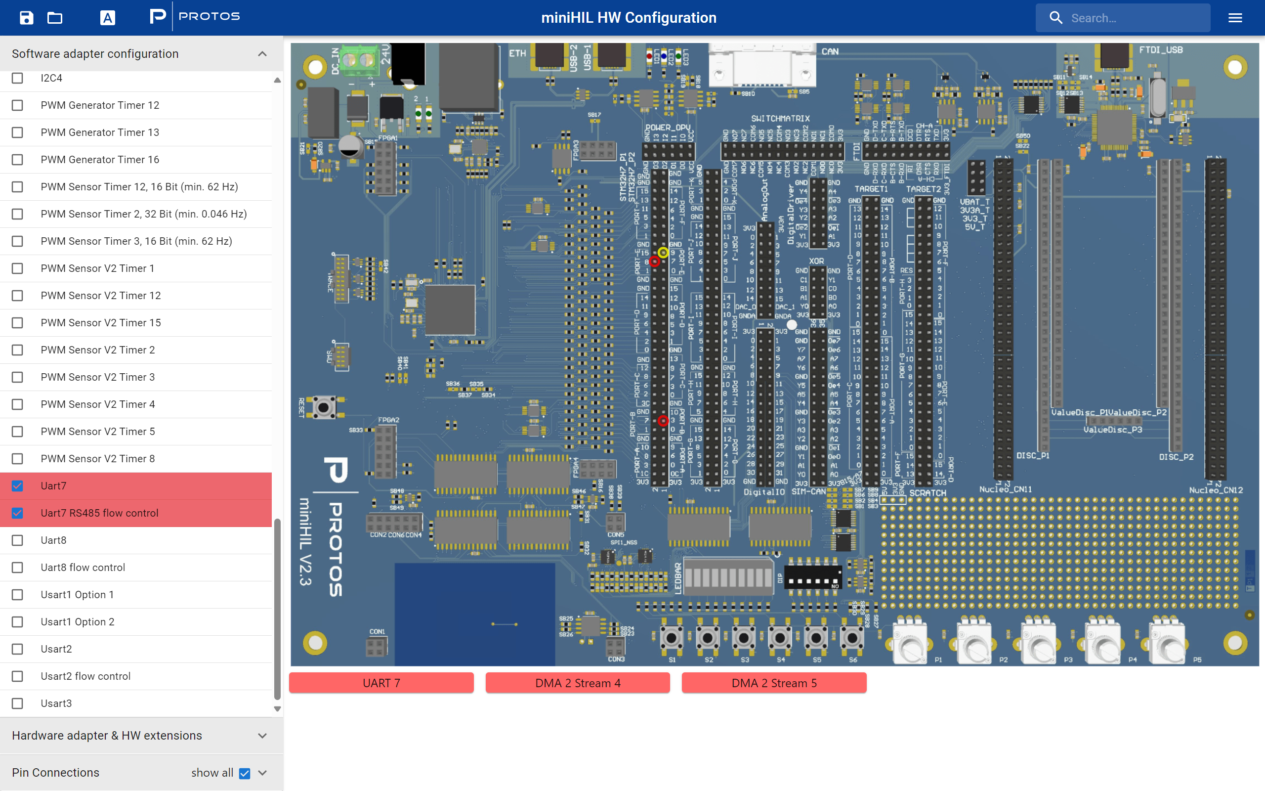
If you proceed to select the conflicting pin, both pins will turn red, indicating a pin configuration conflict that needs to be resolved.
Hardware Adapter & Hardware Extensions
-
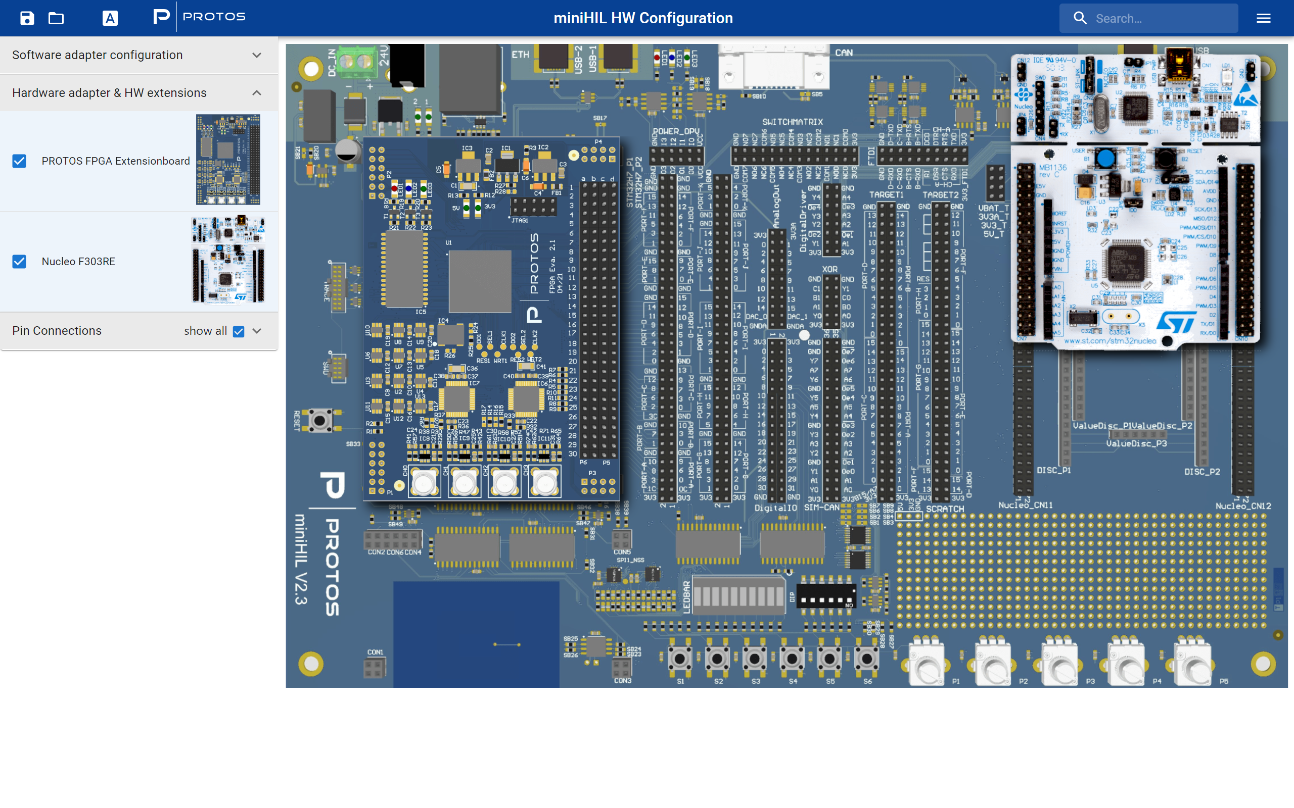
Interactive Pop-out: Clicking on either board will make it pop out in the main board display area, allowing you to view and interact with its specific configurations and settings.
-
Boards Available: PROTOS FPGA Extensionboard, Nucleo F303RE
Pin Connections
-
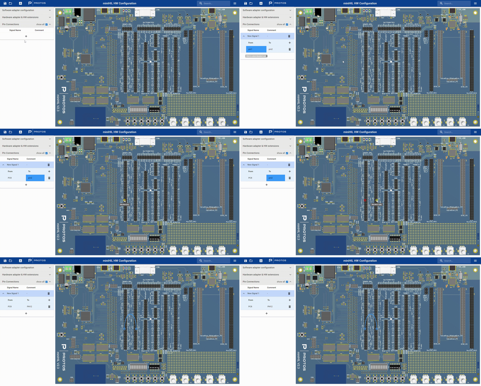
Adding a New Signal: You can add a new signal by providing a name and a comment for better identification and documentation purposes.
-
From and To Sections: In these sections, you will define the source (From) and destination (To) pins for your signal. Selected pins in these sections will turn blue, indicating that they are active and selected. To assign a pin, click on the desired pin on the board.
Searchbar
-
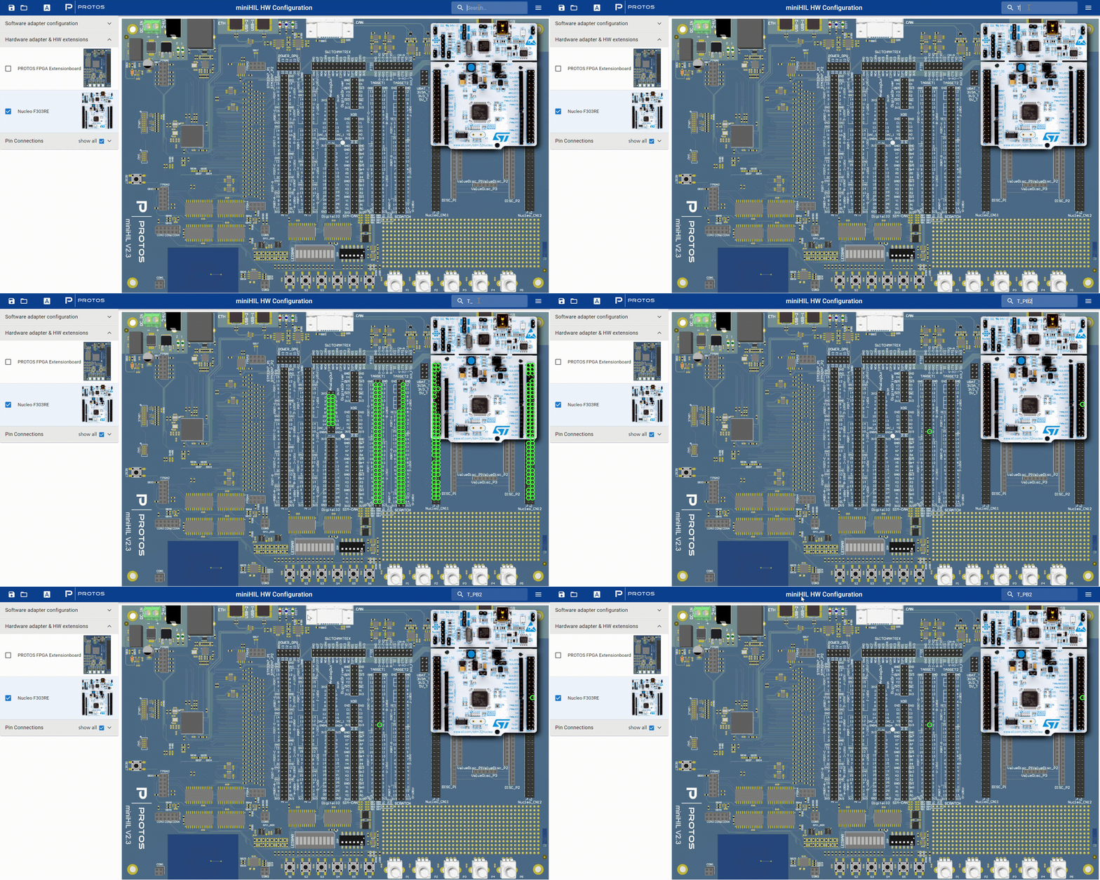
You can use the search bar to find a specific pin. Once found, the pin will be marked with a green circle for easy identification.
Auto Scroll
-
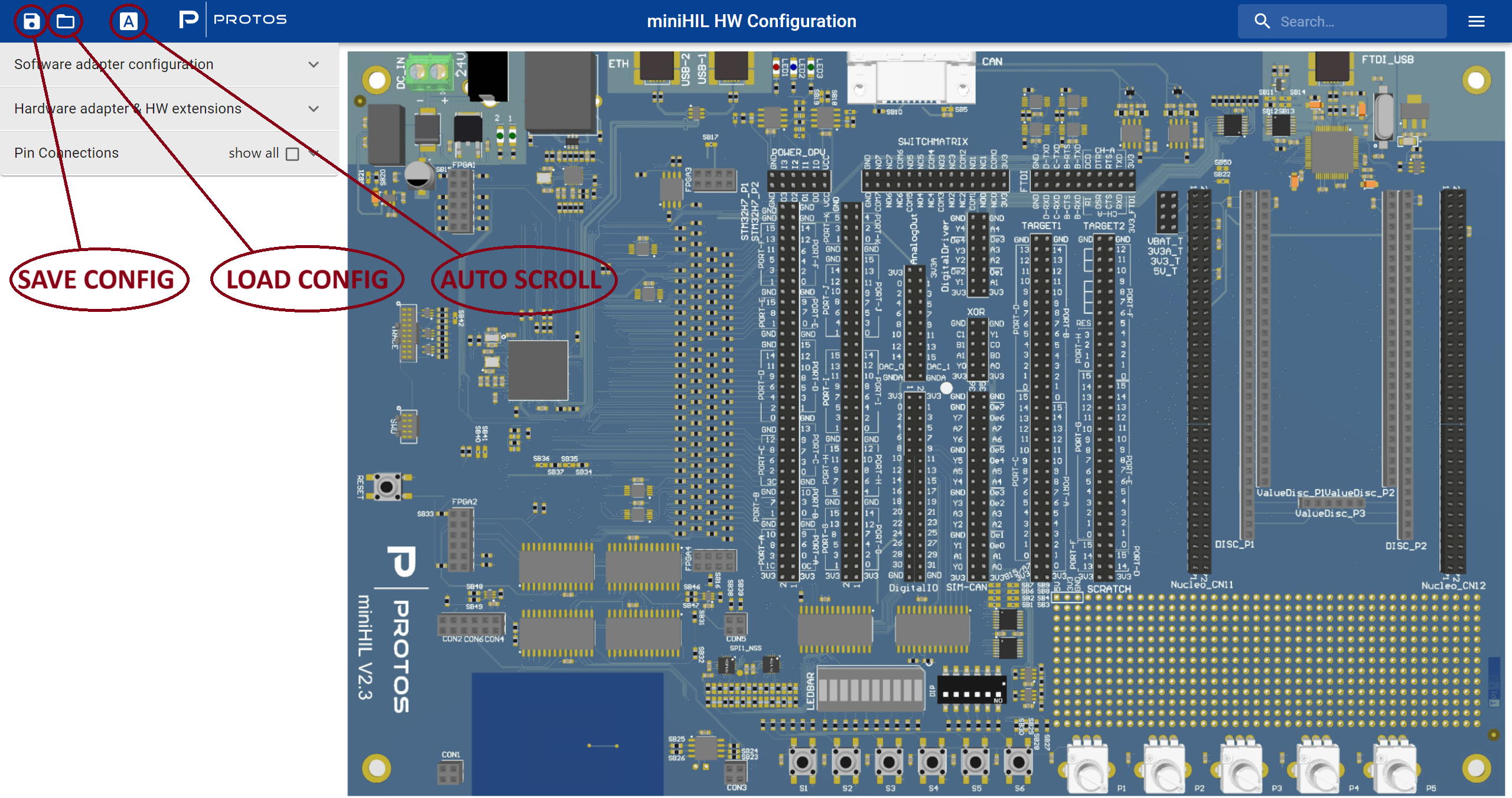
You can activate/deactivate auto-scrolling by clicking the icon to the left of the PROTOS logo. This feature allows the interface to automatically scroll and hover over the corresponding element in the left bar when you point out a software adapter or a pin connection.
Configuration Saving
-
On the upper left side of the screen, click the "Save config" icon to save your configurations as a JSON file.
Configuration Loading
-
To the right of the "Save config" icon, there is a "Load config" icon that allows you to load configurations from a previously saved JSON file.
How to Generate Permanent Hardware Configurations
-
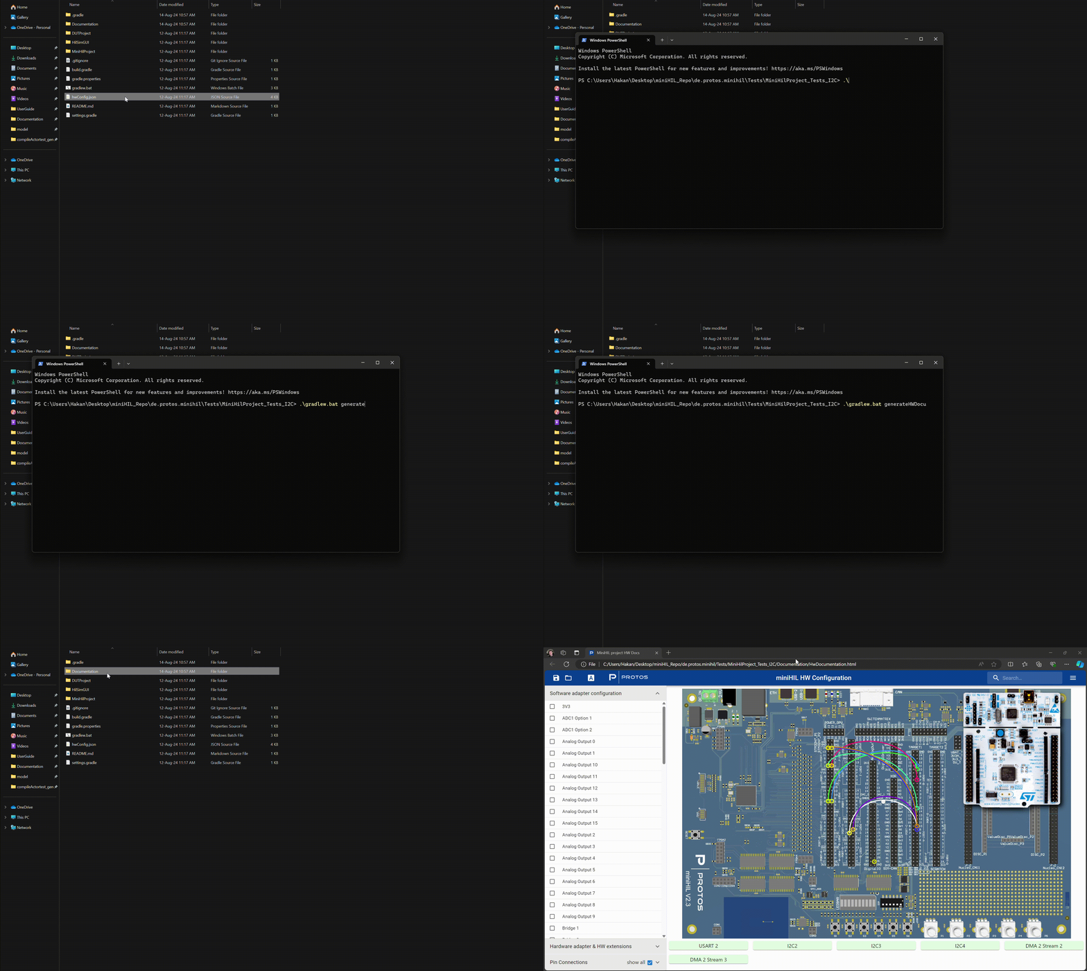
After saving your configurations as a JSON file, you need to copy it to your corresponding project directory.
-
In the project directory, open a command line or terminal and run the following command:
./gradlew.bat generateHWDocu
-
Once the command has been executed, navigate to the Documentation folder within your project directory. Inside, you’ll find the HwDocumentation.html file, which you can open to view the configuration of your project.
-
This interactive interface allows for easy monitoring of your miniHIL hardware setup, ensuring that all pin connections and signal assignments are clearly visualized and managed effectively.