miniHIL Getting Started Tutorial 
Learning Objectives
-
To understand the basic skills required to use and navigate around the IDE. Skills covered:
-
Creating a new project
-
Using Textual view and Structural view
-
Building and Flashing examples on the miniHIL board
-
-
To understand the basic concepts of ROOM and how to implement them in a project. Concepts covered:
-
Actors
-
Ports
-
Protocols
-
Bindings
-
State Machines
-
Services and SAP’s
-
Setup the workspace
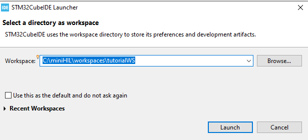
Two miniHIL projects can not share the same workspace, so a new workspace must be created in order to work on another miniHIL project.
Create a new Workspace at C:\miniHIL\workspaces\tutorialWS. (or give it any other name you find suitable)
If you haven’t already done it, extract the Project for this Tutorial.
Then import the project into your "tutorialWS" workspace.
Navigating the miniHIL project
Let’s first familiarize ourselves with the project structure.
Open up the ROOM model of the miniHIL platform by going to the Project Explorer view and navigating to MiniHILProject → model-user → MiniHilProject.room. Double click on MiniHilProject.room to open it. You should be greeted with something like this:
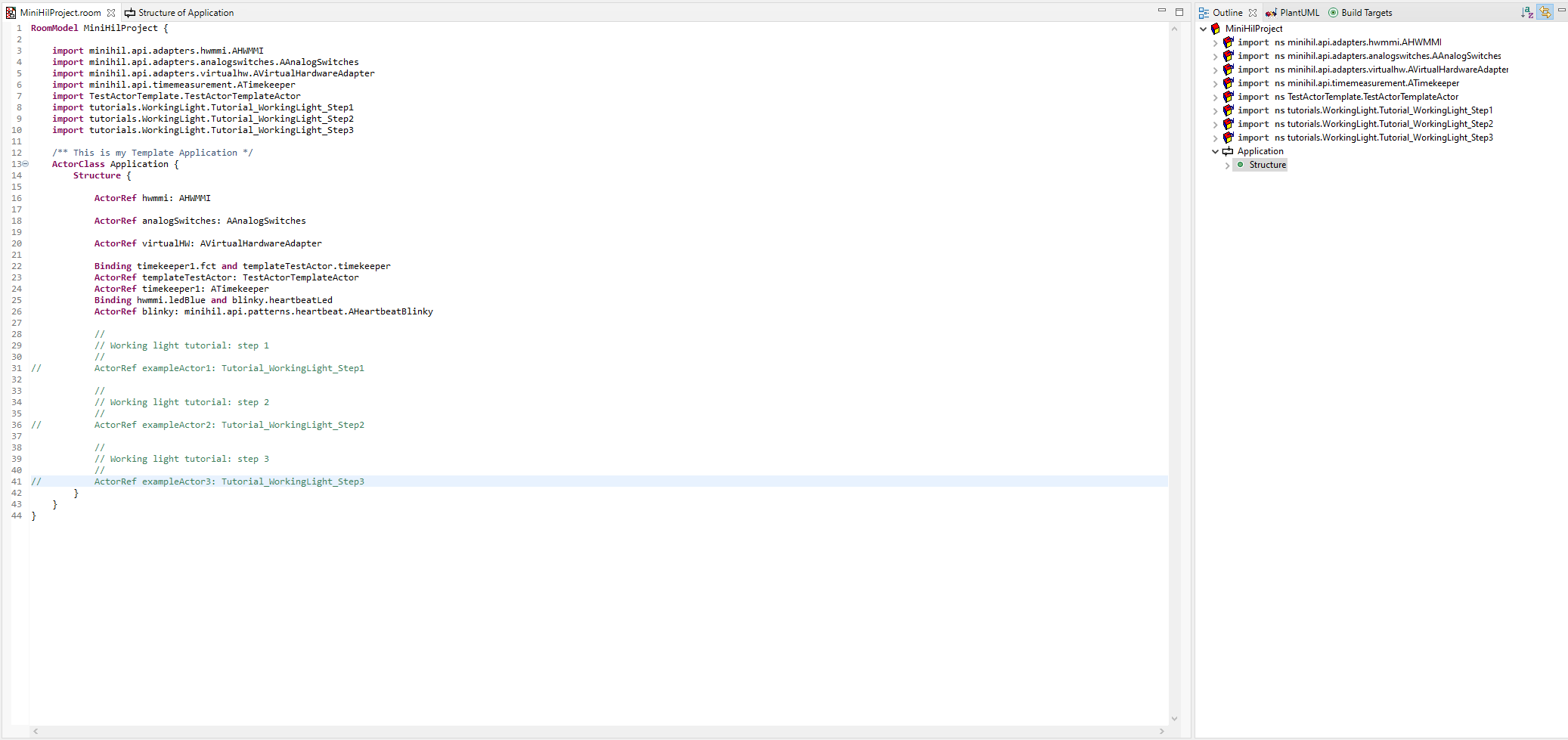
This is the main file that will contain the content of your application. While the code content in this Textual View file may appear unclear to you now, it’ll be explained later in the tutorial. A better way to understand what’s happening here, is to open up the Structural View of "Application".
There are two ways you can enter this view:
-
Select the line containing
ActorClass Application {and pressAlt+S. -
In the Outline view on the right of the editor, right click on Application and click
Edit Structure. If you can’t find this view, go toWindow→Perspective→Reset Perspective.
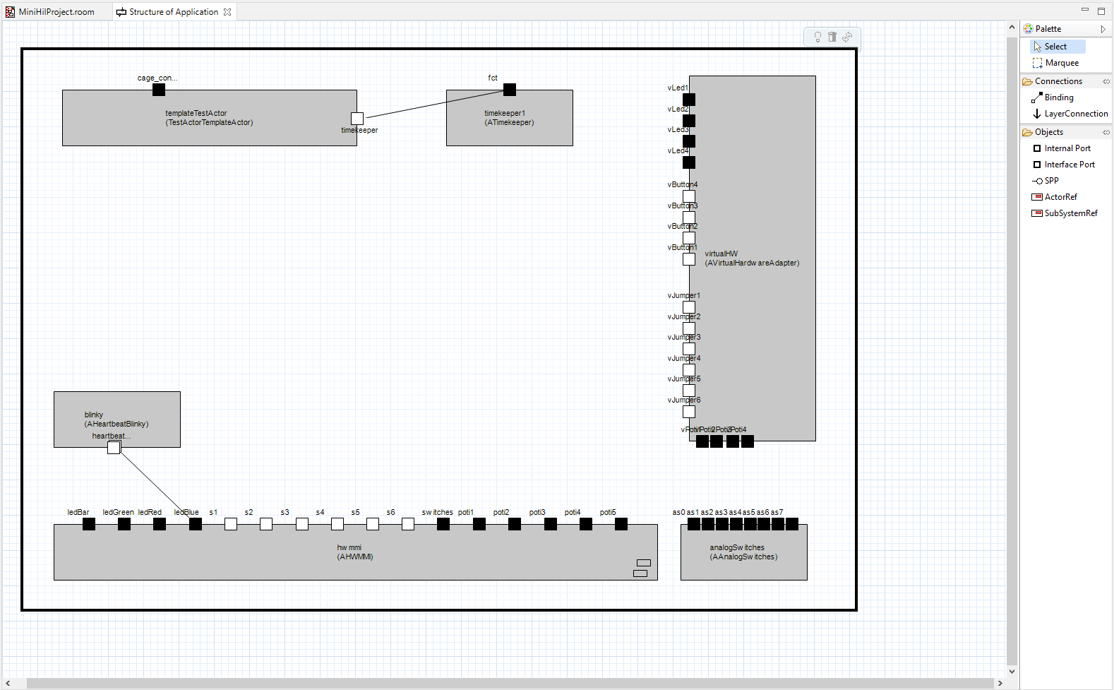
This is the Structural view, which provides a graphical representation of the project. The blocks inside the large rectangle are Actors, which are essentially the fundamental building blocks of miniHIL (you’ll learn about Actors and how to create them in the following steps). You can drag these blocks around the canvas and rearrange them as you please.
During development it’s sometimes better to use this view for certain tasks such as creating bindings between ports (covered in a later step). For now just keep in mind that both the Textual view and the Structural view represent the same thing, so changes that are made in the Structural view will show up in the Textual view and vice versa, so changes made in one view will result in changes in the other view.
Go back to the textual view by clicking the MiniHilProject.room tab at the top of the editor. Sometimes you’ll want to find the declaration of a class/variable that’s declared in another library.
To find a class/variable’s declaration, either highlight the class/variable and press F3 or right click the class/variable and select Open Declaration or Ctrl+Click it.
Step 1 - An Introduction to Actors
This step introduces the concept of Actors, a fundamental building block in ROOM, and how they are used in miniHIL. In essence, an Actor is a representation of an object as a logical machine with defined behavior. Its structure, behavior and protocols are all defined within an element called an ActorClass.
Each step of the WorkingLight has been written as separate Actors and each of their ActorClasses can be found in MiniHilProject/tutorials/WorkingLight.room. Open this file and have a quick look at each step and how they’ve been implemented as ActorClasses.
Declaring an Actor
Now return to MiniHilProject.room. Under the main body of ActorClass Application, there should be a commented line ActorRef workingLight_Step1: Tutorial_WorkingLight_Step1. Uncomment this line and then change to the Structural View (Alt-S). You should be able to see a new block appear representing this new ActorClass declaration!
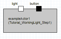
Let’s go over what just happened. An Actor Reference (ActorRef) to the actor class Tutorial_WorkingLight_Step1 was declared and was given the name exampleActor1. It can now interact with other Actors in our project.
Now let’s take a look at the internal workings of the WorkingLight_Step1 actor. Open the WorkingLight.room by using the Project Explorer tab on the left side of the window or alternatively go to the line containing Tutorial_WorkingLight_Step1 that you just uncommented and open its declaration.
Now navigate to the line containing ActorClass Tutorial_Workinglight_Step1 and look at the ActorClass. You’ll see the 3 main components that make up an ActorClass:
Ports, Protocols and Bindings
As mentioned briefly earlier, ports are the interaction points whereby the actor can interact with elements outside of itself. They operate by following an interface description called a Protocol, which is formally defined set of incoming and outgoing messages. Each port has exactly one protocol associated with it, but many ports can share the same protocol.
Ports are also classified into two types: Standard and Conjugated. This is to address the directional nature of protocols, which is necessary for example when two actors communicate and the incoming messages for one actor are the outgoing messages for the other, and vice versa. To summarize:
This tutorial won’t cover the how to write your own protocols, however for a quick idea of how protocols are constructed take a look at the protocol declaration found at SimModelLib/model/minihil/api/onoff.room.
The ports used in this Step use this exact protocol called POnOff, which as the name sugests, provides a simple On/Off behavior. The POnOff protocol provides incoming Messages on() and off() and outgoing Message done().
The two ports, light and button, use this POnOff protocol and are defined in the Interface as well as the Structure of the workingLight_Step1 Actor. +In the Interface section the Port button is a standard port, which means it can handle the incoming Messages on() and off() as incoming Messages. In the interface section the Port light is defined as a conjugated port, which means it can handle the Messages on() and off() as outgoing Messages.
These ports can also be seen visually using the structural view, as small, labelled squares contained in the actor. You can drag these around on the actor to make binding positioning easier.
Creating State Machines
Every actor in ROOM has a behavior which is described by a finite state machine.
The State Machine is defined in the Behavior section of the Actor Class, which like the Structure section, has a graphical and textual view. Creating a State Machine is best done in the graphical view, which can be entered in two ways:
-
To enter this view from the Structural View, right click the actor
workingLight_Step1and selectOpen Ref Behavior. -
To enter this view from the Textual View, select the line containing
ActorClass Tutorial_WorkingLight_Step1 {and pressAlt+B.
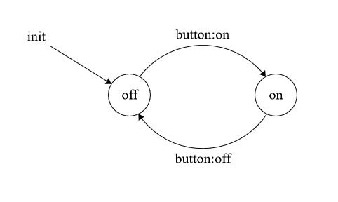
You should be greeted with a state diagram, modelled like the one above with two states and 3 transitions. The two arrows connecting the two states might appear on top of each other upon the initial load, but can be moved around by clicking the line and dragging the node out.
The two states in the diagram are WorkingLightOn and WorkingLightOff. Double-clicking on a state will open up its "Edit State" window. This window contains the state’s entry and exit code, which describes what is executed when the Actor enters and exits the state respectively. The state’s entry and exit code can be viewed and edited here.
In WorkingLightOff both entry and exit codes should be empty as it’s essentially the idle state, while in WorkingLightOn the light is turned on and off upon entry and exit respectively. Creating your own states is a simple matter of clicking the State option on the Palette window on the right and clicking anywhere on the canvas. This is demonstrated in the video snippet below.
The three transitions in the diagram are simply named init, tr0, tr1. Similarly to states, double-clicking on the label of the transition will open up its "Edit Transition" window. The transition is sensitive to triggers, which can be configured in this window. For instance, workingLightOff contains the transition tr0 which is sensitive to the trigger on:button. Therefore when the button receives the on message, it will trigger transition tr0 and hence cause the Actor to transition to the state workingLightOn. As well as having triggers, transitions have action code which executes when the transitions occur. Creating transitions is very similar to creating states, select the transition option on the Palette window and then click and drag between states. This is demonstrated in the video snippet below.
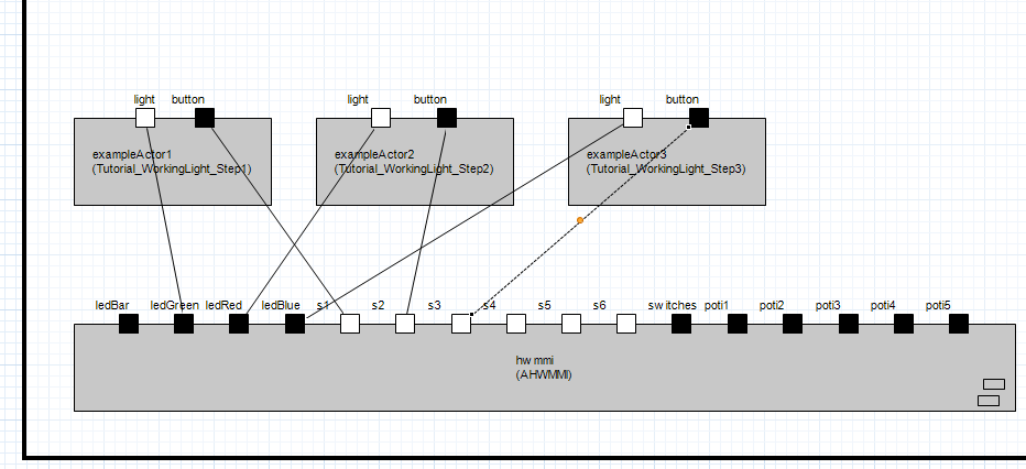
This actor should be connected to the Hardware Abstraction Actor (hwmmi), so that the buttons and LEDs on the miniHIL board can be used. Connecting the ports between actors is simple, select the Binding option in the panel on the right and then click on the source port. All available ports that can be connected should be highlighted in a green bounding box, then you can simply click the destination port that you want to connect to. Now connect the light port to any LED-Port and then button to s1. You may have to delete or comment out an existing binding from another example.
Build and Flash onto the miniHIL board
Now that the code has been written, it is ready to be built and flashed onto the miniHIL board. You can see in the "Quick Start" part of the User Guide how to set up your hardware.
To build and flash the project, select build-debug-STLink in the run configuration dropdown menu. Then click the debug button to launch the debug mode.
Entering debug mode will cause the Eclipse windows to rearrange and as it runs the console window at the bottom should display the status of the build/flash process.
You should now see the board LEDs initialize. Verify that the working light functionality is implemented correctly by pressing the S1 switch. You should see the LED toggle with your button presses. Now that the build has been flashed onto the miniHIL board, exit the debugger by pressing the terminate button (it has a red square for an icon) on the toolbar at the top of the window.
Step 2 - Adding a timeout
In Step 1 the simplest possible Working Light was modelled in miniHIL. This step will add a little bit more functionality to the base working light.
The behavior implemented in this step is a simple timeout, where pressing the button will cause the light to turn on for 1 second, before shutting off. This step is implemented as another ActorClass, therefore, a new ActorRef needs to be declared for this new class.
Below the ActorRef of step 1 in miniHILProject.room, the ActorRef’s for steps 2 and 3 should be commented out. Uncomment the line with Tutorial_WorkingLight_Step2 by removing the // at the beginning of the line.
You can see the changes made in Step2 by opening its declaration. The Interface is identical with the first step, however there are a few differences in the Structure and Behavior.
In Structure, a new element is declared here which is called a Service Access Point (SAP). This introduces you to the concept of services, which for the purposes of this tutorial step are functions that don’t require an explicit binding to access the Actors state. Since the modelling system used in miniHIL is inherently hierarchial (i.e. actors on the same level can interact with each other, but require a port-port connection to interact with actors that are on a different level). What services use instead are Service Access Points (SAPs) and Service Provision Points (SPPs), where SAPs provide access for an Actor to access the SPP of a service, which is where the service is "provided".
Services are typically functions that are required by multiple actors. Using services for them reduces the number of bindings present in the Structural view of the application, as the actors that require it won’t need them, thus de-cluttering the view. The service being provided here is the PTimer service, which is used to achieve the 1 second timeout in the program.
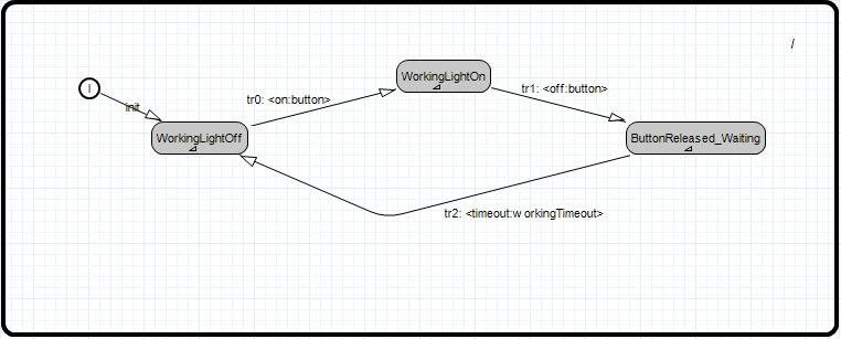
The Behavior also has an added state called ButtonReleased_Waiting.
Connect the light binding of Step2 to ledBlue and the button binding to s2. Now rearrange the bindings of Step 1 in the structural view to accomodate for the new ActorClass. Change the light binding of Step1 to ledRed, so that the LEDs align with the buttons. You may have to delete or comment out an existing binding from another example.
Now flash the code once again onto the miniHIL board. Verify that the implemented behavior is correct by pressing Switch 2 on the board and seeing if the LED remains on for 1 second after releasing the switch.
In this tutorial, the behavior of the switch was verified manually (i.e. you looked at the light to see if it stayed on or not). A primary benefit of the miniHIL board is its capability for running automated tests, so that all combinatorial paths of execution can be evaluated quickly. This tutorial doesn’t cover writing automated tests, but is covered in the more advanced tutorials.
Step 3 - Implementing debounce functionality
In this step the Working Light is developed further by adding in a debouncing function and is implemented in another independent ActorClass. Button debouncing is a commonly used technique in embedded platforms, to ensure that the extra signal "bounces" from a single button push aren’t registered as multiple button toggles. While there exist many algorithms used to address this issue, the debouncing function used in this step will simply use a timeout and check if the button is released longer than the timeout before turning the light off. Essentially, a small extension to the timeout function introduced in step 2.
Once again, the Step 3 ActorRef needs to be declared in miniHILProject.room in order for it to be used. Uncomment the line with Tutorial_WorkingLight_Step3 found below the Step2 declaration from the previous step. Then go to the structural view and bind the light and the button of the new Actor to the remaining LED on the hw actor (ledGreen).
The only difference in this step is a small change in the Actor’s behavior. Open up the Actors behavior view and take a look at the loop created between states ButtonReleased_Waiting and WorkingLightOn using the transitions tr3 and tr1. Now double click on tr3 and look at its Action Code.
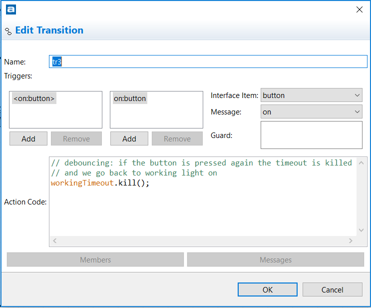
While the state machine is in the ButtonReleased_Waiting state, the transition tr3 triggers when the button goes to the off state. As you can see in the Action Code, the transition stops the timeout and returns to the WorkingLightOn state, thus completing the debouncing loop. This means that the light will be robust to spurious button bounces and instead only turn off when the timeout is successfully reached without intermediate button bounces. Compare this to step 2, where pressing and holding the button, quickly releasing it and holding it again will result in the light still turning off despite the button still being held down.
Flash the code once more onto the miniHIL board and play around with the 3 Working Light setups with switches 1,2 and 3.
Tutorial Summary
You should now be able to:
-
Setup your own project from the the template project
-
Write your own ActorClass and use them in an application
-
Create and change bindings to connect actors together
-
Build and Flash to the miniHIL board
And that’s what you’ll need to get started with miniHIL! Try out some of the more advanced tutorials to learn about the other features of miniHIL.
Typical Issues
-
I closed a view in the Eclipse IDE and now I can’t get it back!
Window → Perspective → Reset Perspective