Model Library
SimModelLib.
Platform Services
The following protocols are available as a platform service.
PLogger
Protocol for logging text messages.
This protocol is a service and can be accessed via an SAP. It provides PortOperations to log (formatted) messages.
logger.log("message");
logger.logF("counter %d", 100);
Conjugated PortClass
| Name | Return type | Arguments | Description |
|---|---|---|---|
log |
void |
message: char |
Logs a simple message. Appends line separator. |
logF |
void |
format: char, args: voidType |
Logs a formatted message with arguments. Appends line separator. |
PTimer
Defines the communication protocol to control a single timer.
| Message | Type | Description |
|---|---|---|
startTimer |
uint32 |
Start a timer that notifies every time the specified period in milliseconds expires. This has no effect if there is already an active timer or timeout. |
startTimeout |
uint32 |
Start a timeout that notifies once when the specified duration in milliseconds expires. This has no effect if there is already an active timer or timeout. |
kill |
void |
Stop an active timer or timeout. This has no effect if neither a timer nor a timeout is active. |
_startTimer |
DStartTimer |
|
_startTimeout |
DStartTimer |
| Message | Type | Description |
|---|---|---|
timeout |
void |
Inform about an expired timer or timeout. |
_timeout |
uint16 |
PTracer
Protocol to control tracing.
| Message | Type | Description |
|---|---|---|
start |
void |
Start recording traces |
stop |
void |
Stop recording traces |
flush |
void |
Write recorded traces and create diagram |
| Message | Type | Description |
|---|---|---|
done |
void |
flush() done |
Common Protocols
POnOff
| Message | Type | Description |
|---|---|---|
on |
void |
|
off |
void |
| Message | Type | Description |
|---|---|---|
done |
void |
Regular PortClass
| Name | Return type | Arguments | Description |
|---|---|---|---|
isPortStateOn |
uint8 |
||
isPortStateOff |
uint8 |
PAdc
| Message | Type | Description |
|---|---|---|
start |
uint8 |
|
stop |
void |
| Message | Type | Description |
|---|---|---|
newValue |
uint32 |
Voltage in mV |
MMI
AHWMMI
Structure
| Name | Protocol | Type | Kind | Multiplicity | Description |
|---|---|---|---|---|---|
ledBar |
PLedBarCtrl |
regular |
relay |
1 |
|
ledGreen |
POnOff |
regular |
relay |
1 |
|
ledRed |
POnOff |
regular |
relay |
1 |
|
ledBlue |
POnOff |
regular |
relay |
1 |
|
s1 |
POnOff |
conjugated |
relay |
1 |
|
s2 |
POnOff |
conjugated |
relay |
1 |
|
s3 |
POnOff |
conjugated |
relay |
1 |
|
s4 |
POnOff |
conjugated |
relay |
1 |
|
s5 |
POnOff |
conjugated |
relay |
1 |
|
s6 |
POnOff |
conjugated |
relay |
1 |
|
switches |
PDipSwitchesCtrl |
regular |
relay |
1 |
|
poti1 |
PAdc |
regular |
relay |
1 |
|
poti2 |
PAdc |
regular |
relay |
1 |
|
poti3 |
PAdc |
regular |
relay |
1 |
|
poti4 |
PAdc |
regular |
relay |
1 |
|
poti5 |
PAdc |
regular |
relay |
1 |
PLedBarCtrl
| Message | Type | Description |
|---|---|---|
setPattern |
uint16 |
PDipSwitchesCtrl
| Message | Type | Description |
|---|---|---|
getPattern |
void |
| Message | Type | Description |
|---|---|---|
pattern |
uint32 |
Analog and Digital IO
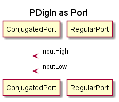
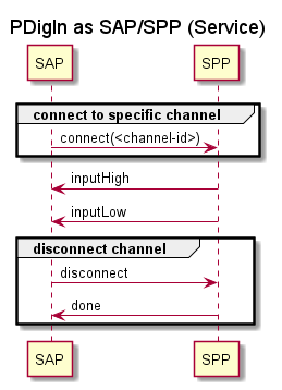
PDigIn
Protocol for access to digital hardware input
Works via Ports and SAPs. For SAPs the connect message has to be called to specify a specific input channel.
| Message | Type | Description |
|---|---|---|
connect |
EUser_DigitalInputs |
connect to a specific input channel - only needed for SAPs |
disconnect |
void |
disconnect from input channel - only needed for SAPs |
requestLastState |
void |
requests a new message with the actual pin state. Same as "getLastState" but asynchronous |
| Message | Type | Description |
|---|---|---|
inputHigh |
void |
notification for change to input high |
inputLow |
void |
notification for change to input low |
done |
void |
reply to disconnect |
disconnected |
void |
may be sent as reply to requestLastState, also may be sent in case of disconnect during connect (if already connected) |
Conjugated PortClass
| Name | Return type | Arguments | Description |
|---|---|---|---|
getLastState |
uint8 |
synchronous operation to poll last received state of input |
EUser_DigitalInputs
The literals of this enumeration are of type int.
| Name | Value | Hex Value | Binary Value |
|---|---|---|---|
in_08 |
0 |
0x0 |
0 |
in_09 |
1 |
0x1 |
1 |
in_10 |
2 |
0x2 |
10 |
in_11 |
3 |
0x3 |
11 |
in_12 |
4 |
0x4 |
100 |
in_13 |
5 |
0x5 |
101 |
in_14 |
6 |
0x6 |
110 |
in_15 |
7 |
0x7 |
111 |
in_00 |
8 |
0x8 |
1000 |
in_01 |
9 |
0x9 |
1001 |
in_02 |
10 |
0xa |
1010 |
in_03 |
11 |
0xb |
1011 |
in_04 |
12 |
0xc |
1100 |
in_05 |
13 |
0xd |
1101 |
in_06 |
14 |
0xe |
1110 |
in_07 |
15 |
0xf |
1111 |
UNDEFINED |
16 |
0x10 |
10000 |
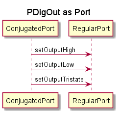
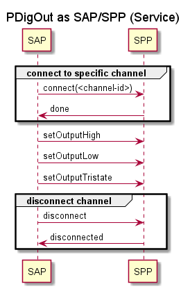
PDigOut
Protocol for access to digital hardware output
Works via Ports and SAPs. For SAPs the connect message has to be called to specify a specific output channel.
| Message | Type | Description |
|---|---|---|
connect |
EUser_DigitalOutputs |
connect to a specific output channel - only needed for SAPs |
disconnect |
void |
disconnect from output channel - only needed for SAPs |
setOutputHigh |
void |
setting output to high |
setOutputLow |
void |
setting output to low |
setOutputTristate |
void |
setting output to tristate |
| Message | Type | Description |
|---|---|---|
done |
void |
reply to connect |
disconnected |
void |
reply to disconnect |
EUser_DigitalOutputs
The literals of this enumeration are of type int.
| Name | Value | Hex Value | Binary Value |
|---|---|---|---|
out_24 |
0 |
0x0 |
0 |
out_25 |
1 |
0x1 |
1 |
out_26 |
2 |
0x2 |
10 |
out_27 |
3 |
0x3 |
11 |
out_28 |
4 |
0x4 |
100 |
out_29 |
5 |
0x5 |
101 |
out_30 |
6 |
0x6 |
110 |
out_31 |
7 |
0x7 |
111 |
out_16 |
8 |
0x8 |
1000 |
out_17 |
9 |
0x9 |
1001 |
out_18 |
10 |
0xa |
1010 |
out_19 |
11 |
0xb |
1011 |
out_20 |
12 |
0xc |
1100 |
out_21 |
13 |
0xd |
1101 |
out_22 |
14 |
0xe |
1110 |
out_23 |
15 |
0xf |
1111 |
UNDEFINED |
16 |
0x10 |
10000 |
PAnIn
| Message | Type | Description |
|---|---|---|
connect |
EUser_AnalogInputs |
connect to a specific output channel - only needed for SAPs |
disconnect |
void |
disconnect from output channel - only needed for SAPs |
start |
uint32 |
start periodical update of input in milli seconds (every n milliseconds) |
stop |
void |
stop periodical |
| Message | Type | Description |
|---|---|---|
done |
void |
reply to connect |
disconnected |
void |
reply to disconnect |
newValue |
uint32 |
periodical message with new value (only after call of start) |
error |
void |
error notification |
EUser_AnalogInputs
The literals of this enumeration are of type int.
| Name | Value | Hex Value | Binary Value |
|---|---|---|---|
poti_00 |
0 |
0x0 |
0 |
poti_01 |
1 |
0x1 |
1 |
poti_02 |
2 |
0x2 |
10 |
poti_03 |
3 |
0x3 |
11 |
poti_04 |
4 |
0x4 |
100 |
UNDEFINED |
5 |
0x5 |
101 |
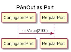
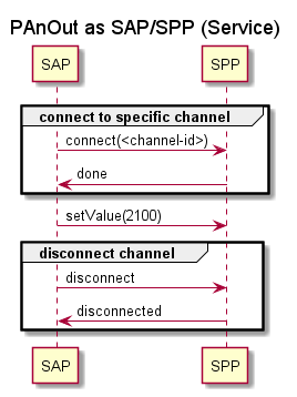
PAnOut
Protocol for access to analog hardware output
Works via Ports and SAPs. For SAPs the connect message has to be called to specify a specific output channel.
| Message | Type | Description |
|---|---|---|
connect |
EUser_AnalogOutputs |
connect to a specific output channel - only needed for SAPs |
disconnect |
void |
disconnect from output channel - only needed for SAPs |
setValue |
uint32 |
setting output to a specific value in milli volt (e.g. 2100 = 2100 mV = 2.1 V) |
| Message | Type | Description |
|---|---|---|
done |
void |
reply to connect |
disconnected |
void |
reply to disconnect |
EUser_AnalogOutputs
The literals of this enumeration are of type int.
| Name | Value | Hex Value | Binary Value |
|---|---|---|---|
out_00 |
0 |
0x0 |
0 |
out_01 |
1 |
0x1 |
1 |
out_02 |
2 |
0x2 |
10 |
out_03 |
3 |
0x3 |
11 |
out_04 |
4 |
0x4 |
100 |
out_05 |
5 |
0x5 |
101 |
out_06 |
6 |
0x6 |
110 |
out_07 |
7 |
0x7 |
111 |
out_08 |
8 |
0x8 |
1000 |
out_09 |
9 |
0x9 |
1001 |
out_10 |
10 |
0xa |
1010 |
out_11 |
11 |
0xb |
1011 |
out_12 |
12 |
0xc |
1100 |
out_13 |
13 |
0xd |
1101 |
out_14 |
14 |
0xe |
1110 |
out_15 |
15 |
0xf |
1111 |
UNDEFINED |
16 |
0x10 |
10000 |
Analog Switches
AAnalogSwitches
Structure
| Name | Protocol | Type | Kind | Multiplicity | Description |
|---|---|---|---|---|---|
as0 |
POnOff |
regular |
external |
1 |
|
as1 |
POnOff |
regular |
external |
1 |
|
as2 |
POnOff |
regular |
external |
1 |
|
as3 |
POnOff |
regular |
external |
1 |
|
as4 |
POnOff |
regular |
external |
1 |
|
as5 |
POnOff |
regular |
external |
1 |
|
as6 |
POnOff |
regular |
external |
1 |
|
as7 |
POnOff |
regular |
external |
1 |
Behavior
- Top Level State
-
- state0
-
(no description) -
Testing
PTestControl
Simple protocol to start or stop tests.
| Message | Type | Description |
|---|---|---|
start |
void |
Start test execution. |
abort |
void |
Abort test execution. |
| Message | Type | Description |
|---|---|---|
done |
boolean |
Reply after test execution is done. Status is true if all tests have passed. |
Simulator GUI
AVirtualHardwareAdapter
TODO Documentation
Structure
| Name | Protocol | Type | Kind | Multiplicity | Description |
|---|---|---|---|---|---|
vPoti1 |
PAdc |
regular |
external |
1 |
|
vPoti2 |
PAdc |
regular |
external |
1 |
|
vPoti3 |
PAdc |
regular |
external |
1 |
|
vPoti4 |
PAdc |
regular |
external |
1 |
|
vButton1 |
POnOff |
conjugated |
external |
1 |
|
vButton2 |
POnOff |
conjugated |
external |
1 |
|
vButton3 |
POnOff |
conjugated |
external |
1 |
|
vButton4 |
POnOff |
conjugated |
external |
1 |
|
vLed1 |
POnOff |
regular |
external |
1 |
|
vLed2 |
POnOff |
regular |
external |
1 |
|
vLed3 |
POnOff |
regular |
external |
1 |
|
vLed4 |
POnOff |
regular |
external |
1 |
|
vJumper1 |
POnOff |
conjugated |
external |
1 |
|
vJumper2 |
POnOff |
conjugated |
external |
1 |
|
vJumper3 |
POnOff |
conjugated |
external |
1 |
|
vJumper4 |
POnOff |
conjugated |
external |
1 |
|
vJumper5 |
POnOff |
conjugated |
external |
1 |
|
vJumper6 |
POnOff |
conjugated |
external |
1 |
| Name | Type | Description |
|---|---|---|
potiValues |
uint32 |
Behavior
- Top Level State
-
- handleDataConfig
-
(no description) -
ATraceButton
Button to activate MSC tracing while button is held.
Structure
| Name | Protocol | Type | Kind | Multiplicity | Description |
|---|---|---|---|---|---|
button |
POnOff |
regular |
external |
1 |
Behavior
- Top Level State
-
- idle
-
(no description)
- active
-
(no description) -
UART
PFixedSizePacketCommunication
packet communication for sending and receiving static packages (fixed size)
| Message | Type | Description |
|---|---|---|
sendPacket |
DFixedSizePacket32Byte |
sending a static data package |
| Message | Type | Description |
|---|---|---|
receivedPacket |
DFixedSizePacket32Byte |
receiving a static data Package |
sendDone |
void |
response to sendPackage |
DFixedSizePacket32Byte
Data packet for packet communication with a maximum of 32 bytes
| Name | Type | Description |
|---|---|---|
len |
uint16 |
length of the data |
buffer |
uint8 |
data buffer |
| Name | Return type | Arguments | Description |
|---|---|---|---|
setData |
void |
length: uint16, data: uint8 |
deep copy data to buffer |
DUartConfiguration
DataClass used to configure a sync-byte synchronized UART adapter for fixed size packages
| Name | Type | Description |
|---|---|---|
packet_size |
uint16 |
packet size for fixed size package protocols |
startByte |
uint8 |
The start byte to use for each packet (used for synchronization) |
EParity
Parity setting for UART communication
The literals of this enumeration are of type int.
| Name | Value | Hex Value | Binary Value |
|---|---|---|---|
NONE |
0 |
0x0 |
0 |
EVEN |
1 |
0x1 |
1 |
ODD |
2 |
0x2 |
10 |
EStopBits
Stop Bit settings for UART communication
The literals of this enumeration are of type int.
| Name | Value | Hex Value | Binary Value |
|---|---|---|---|
STOPBITS_0_5 |
0 |
0x0 |
0 |
STOPBITS_1 |
1 |
0x1 |
1 |
STOPBITS_1_5 |
2 |
0x2 |
10 |
STOPBITS_2 |
3 |
0x3 |
11 |
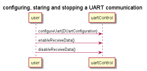
PUartControl
Configuration and control of a UART communication
| Message | Type | Description |
|---|---|---|
configureUart |
DUartConfiguration |
configure UART communication |
enableReceiveData |
void |
start receiving data |
disableReceiveData |
void |
stop receiving data. Depending on the underlying implementation the next received packet might still be delivered. |
| Message | Type | Description |
|---|---|---|
configurationComplete |
void |
Reply once the configuration is completed |
AUart1Adapter
Provides fixed packet size uart communication via a hardware uart interface. Currently it only supports asynchronous operation without additional flow control
NOTE: There can only be one instance of this actor class in your model! as this actor is linked to concrete hardware.
Structure
| Name | Protocol | Type | Kind | Multiplicity | Description |
|---|---|---|---|---|---|
comm |
PFixedSizePacketCommunication |
regular |
relay |
1 |
|
config |
PUartControl |
regular |
relay |
1 |
AUart2Adapter
Provides fixed packet size uart communication via a hardware uart interface. Currently it only supports asynchronous operation without additional flow control
NOTE: There can only be one instance of this actor class in your model! as this actor is linked to concrete hardware.
Structure
| Name | Protocol | Type | Kind | Multiplicity | Description |
|---|---|---|---|---|---|
comm |
PFixedSizePacketCommunication |
regular |
relay |
1 |
|
config |
PUartControl |
regular |
relay |
1 |
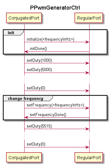
PwmGenerator
PPwmGeneratorCtrl
Protocol to interact with a pwm generator actor
| Message | Type | Description |
|---|---|---|
initialize |
uint32 |
Initializes the timer hardware. Parameter: The desired pwm frequency in Hz |
setDuty |
int16 |
Sets the pwm duty. Parameter: The desired duty times 10000. E.g. 10000 = 100%, 5000 = 50%, 2500 = 25% |
setFrequency |
uint32 |
Sets the desired pwm frequency. This is not synchronized with the currently active pwm -> The wave form will not fluently change from its current frequency to the new one. It is recommended to set the duty to 0% before changing the frequency to avoid undesired intermediate wave forms. |
| Message | Type | Description |
|---|---|---|
initDone |
void |
reply to the initialize message once the hardware is initialized. |
setFrequencyDone |
void |
reply to the setFrequency message once the frequency has been changed. |
APwmGenerator1
A pwm generator. See PPwmGeneratorCtrl for usage instructions. Tested frequencies are 100 Hz to 120 kHz. The duty resolution is gradually lowered above 20 kHz.
This pwm generator uses tim16 and outputs its pwm on pin PF6.
 |
Only one instance of this actor can be used. |
Structure
| Name | Protocol | Type | Kind | Multiplicity | Description |
|---|---|---|---|---|---|
ctrl |
PPwmGeneratorCtrl |
regular |
relay |
3 |
APwmGenerator2
A pwm generator. See PPwmGeneratorCtrl for usage instructions. Tested frequencies are 100 Hz to 120 kHz. The duty resolution is gradually lowered above 20 kHz.
This pwm generator uses tim12 and outputs its pwm on pin PH6.
| |
Only one instance of this actor can be used. |
Structure
| Name | Protocol | Type | Kind | Multiplicity | Description |
|---|---|---|---|---|---|
ctrl |
PPwmGeneratorCtrl |
regular |
relay |
3 |
PwmSensor
PPwmSensorCtrl
Protocol to interact with a pwm sensor actor
| Message | Type | Description |
|---|---|---|
getFrequency |
void |
Requests the current PWM frequency. See frequency reply for more info. |
getDuty |
void |
Requests the current PWM duty. See duty reply for more info. |
getMeasurement |
void |
Requests a single measurement (duty + frequency) |
getMeasurementEveryXms |
uint32 |
Request a measurement (duty + frequency) every X ms |
stopGetMeasurement |
void |
Stop the currently active measurement subscription |
setLowCutOffFrequency |
uint32 |
Set the minimum frequency (in Hz) which you expect the PWM signal to have. This is needed to detect 0 or 100% PWM duty. If you set this too low it takes a long time until a 0 / 100% duty value is detected. If you set it too high, duties other than 0 and 100% will not be detected anymore. |
| Message | Type | Description |
|---|---|---|
params |
DPwmParams |
Pay load is a single measurement (duty + frequency). See duty and frequency reply for info about the encoding and limitations. |
duty |
uint32 |
message pay load is duty (on / period length) times 10000. -> 100% duty -> value = 10000. 50% duty -> value = 5000 |
frequency |
uint32 |
message pay load is PWM frequency in Hz. This value is only reliable if 0% < duty < 100% ! |
DPwmParams
| Name | Type | Description |
|---|---|---|
frequency |
uint32 |
frequency in HZ. This value is only reliable if 0% < duty < 100% ! |
duty |
uint32 |
duty (on / period length) times 10000. -> 100% duty -> value = 10000. 50% duty -> value = 5000 |
APwmSensor1
Measures PWM frequency and duty using a hardware timer. (Tim3)
16 bit timer, 4 MHZ tick frequency. Lowest measurable PWM frequency is ~ 62 Hz
InputPin: PC6
Measurement resolution depends on the frequency of the measured PWM signal. E.g.: 20 kHz PWM -> Res: ~ 0.5 %, 10 kHz PWM -> Res: ~ 0.25 %, 1 kHz PWM -> Res: 0.025 %
Structure
| Name | Protocol | Type | Kind | Multiplicity | Description |
|---|---|---|---|---|---|
ctrl |
PPwmSensorCtrl |
regular |
relay |
2 |
APwmSensor2
Measures PWM frequency and duty using a hardware timer. (Tim2)
32 bit timer, 200 MHZ tick frequency. Lowest measurable PWM frequency is ~ 0.05 Hz
InputPin: PA0
Measurement resolution depends on the frequency of the measured PWM signal. E.g.: 20 kHz PWM -> Res: ~ 0.01 %, 10 kHz PWM -> Res: ~ 0.005 %, 1 kHz PWM -> Res: 0.0005 %
Structure
| Name | Protocol | Type | Kind | Multiplicity | Description |
|---|---|---|---|---|---|
ctrl |
PPwmSensorCtrl |
regular |
relay |
2 |
I2C
AI2CBus2Adapter
Currently only supports I2C Slave simulation
Used Pins: - PF0: I2C2_SDA - PF1: I2C2_SCL
Used I2C Hardware: I2C2
Structure
| Name | Protocol | Type | Kind | Multiplicity | Description |
|---|---|---|---|---|---|
conf |
PI2CBusConfig |
regular |
external |
16 |
Behavior
| Name | Return type | Arguments | Description |
|---|---|---|---|
initI2CHardware |
boolean |
hi2c: I2C_HandleTypeDef, callbacks: I2CPlatformCallbacks |
AI2CBus3Adapter
Currently only supports I2C Slave simulation
Used Pins: - PH8: I2C3_SDA - PH7: I2C3_SCL
Used I2C Hardware: I2C3
Structure
| Name | Protocol | Type | Kind | Multiplicity | Description |
|---|---|---|---|---|---|
conf |
PI2CBusConfig |
regular |
external |
16 |
Behavior
| Name | Return type | Arguments | Description |
|---|---|---|---|
initI2CHardware |
boolean |
hi2c: I2C_HandleTypeDef, callbacks: I2CPlatformCallbacks |
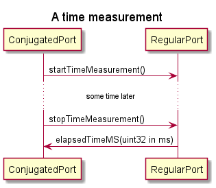
Time measurement
Millisecond pecision timekeeper
(minihil.api.timemeasurement.ATimekeeper)
This actor implements a simple stop watch. It starts taking the time when it receives a startTimeMeasurement message and stops the measurement if a stopTimeMeasurement message is received. The measured time in milliseconds is automatically send out in an elapsedTimeMS message once the stopTimeMeasurement message is received.
NOTE: This time keeper currently does one time keeping operation at a time. An out of order startTimeMeasurement or stopTimeMeasurement message is dropped silently. It is up to the user to avoid conflicting time measurements.
Structure
| Name | Protocol | Type | Kind | Multiplicity | Description |
|---|---|---|---|---|---|
fct |
PTimekeeper |
regular |
external |
1 |
| Name | Type | Description |
|---|---|---|
startTime |
etTime |
Behavior
- Top Level State
-
- idle
-
(no description)
- measuringTime
-
(no description) === The timekeeper protocol (minihil.api.timemeasurement.PTimekeeper)
Protocol for access to a time keeping actor
| Message | Type | Description |
|---|---|---|
startTimeMeasurement |
void |
|
stopTimeMeasurement |
void |
| Message | Type | Description |
|---|---|---|
elapsedTimeMS |
uint32 |
|
timeMeasurementRestarted |
void |
Other
PInterrupt
| Message | Type | Description |
|---|---|---|
event |
void |
Conjugated PortClass
| Name | Return type | Arguments | Description |
|---|---|---|---|
export |
PInterruptConjPort |
||
dispatch |
void |
||
fire |
void |